

 English
 中文简体
中文简体What Makes Cold Room Refrigeration Work — And Why the Condensing Unit Is the Core
Cold room refrigeration is a mechanical system designed to maintain precise low temperatures inside an insulated enclosure for storing perishable goods, pharmaceutical products, or industrial materials. At the heart of every cold room refrigeration system is the condensing unit — the external assembly that drives the entire refrigeration cycle by compressing refrigerant gas, rejecting heat to the outside environment, and circulating cooled refrigerant back to the evaporator inside the cold room. Without a properly sized and functioning condensing unit, no cold room can reliably hold its setpoint temperature, regardless of how well-insulated the structure is.
The refrigeration cycle begins when low-pressure refrigerant vapor is drawn from the evaporator coil inside the cold room into the compressor housed within the condensing unit. The compressor raises both the pressure and temperature of the gas. That hot, high-pressure gas travels to the condenser coil, where a fan blows ambient air across the coil and removes the heat. The refrigerant condenses into a liquid, passes through an expansion device, drops in pressure and temperature, and returns to the evaporator to absorb heat from the cold room interior all over again. This cycle repeats continuously to maintain the target temperature.
Understanding this cycle in depth — and knowing how every component within a condensing unit contributes to it — is essential for anyone specifying, installing, or maintaining a cold room refrigeration system.
Cold Room Refrigeration System Types and Their Operating Ranges
Cold room refrigeration systems are broadly classified by their operating temperature range, which directly determines the type of condensing unit and refrigerant required. Getting this classification right from the start prevents costly mistakes in equipment selection.
Medium-Temperature Cold Rooms (Coolers)
Medium-temperature cold rooms typically operate between +2°C and +10°C. These are used for fresh produce, dairy products, beverages, and floral storage. The condensing unit for a medium-temperature application uses a standard single-stage compressor, and common refrigerants include R-404A, R-448A, R-449A, and R-134a. Suction pressure in medium-temperature systems generally runs between 2 and 4 bar gauge, allowing the compressor to operate efficiently without extreme pressure ratios.
Low-Temperature Cold Rooms (Freezers)
Low-temperature cold rooms maintain temperatures between -18°C and -25°C, covering most commercial and industrial frozen food storage. These systems require condensing units with compressors capable of handling high compression ratios. Because suction pressure at -25°C with R-404A may drop to around 0.5 bar absolute, many manufacturers offer two-stage or compound condensing units for these applications to protect compressor efficiency and longevity.
Ultra-Low Temperature Systems
For pharmaceutical cold rooms, research laboratories, and specific industrial processes, temperatures below -40°C are required. These systems typically use cascade refrigeration — two separate refrigeration circuits linked by a heat exchanger. The high-stage condensing unit rejects heat to the environment using a conventional refrigerant, while the low-stage condensing unit uses a refrigerant with a very low boiling point, such as R-508B or CO₂, to achieve the required ultra-low temperatures.
| Cold Room Type | Temperature Range | Typical Refrigerant | Condensing Unit Type | Common Applications |
|---|---|---|---|---|
| Cooler | +2°C to +10°C | R-448A, R-134a | Single-stage | Produce, dairy, beverages |
| Freezer | -18°C to -25°C | R-404A, R-449A | Single or two-stage | Frozen food, ice cream |
| Ultra-Low | -40°C to -80°C | R-508B, CO₂ | Cascade system | Pharma, research labs |
| Controlled Atmosphere | -1°C to +4°C | R-744 (CO₂), R-134a | Single-stage precision | Long-term fruit storage |
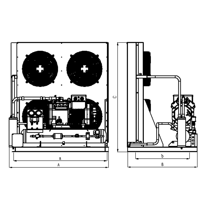
Anatomy of a Condensing Unit: Components and Their Functions
A condensing unit is a self-contained assembly that packages several critical refrigeration components into a single, pre-wired, pre-charged unit ready for field connection to the evaporator. Understanding what is inside the unit helps technicians diagnose problems and helps buyers compare specifications meaningfully.
The Compressor
The compressor is the most critical and most expensive component in any condensing unit. It is the mechanical pump that moves refrigerant through the entire system. For cold room refrigeration, the three most common compressor types are:
- Reciprocating (piston) compressors — Robust, widely available, and relatively inexpensive to replace. Common in smaller cold rooms from 1 kW to 20 kW. Hermetic reciprocating compressors from brands like Embraco, Tecumseh, and Danfoss dominate the small commercial cold room market.
- Scroll compressors — Quieter and more efficient than reciprocating compressors at part load. Widely used in medium to large cold rooms. Copeland scroll compressors from Emerson are arguably the most specified in commercial cold room refrigeration globally.
- Semi-hermetic compressors — Serviceable in the field, meaning the motor windings and pistons can be rebuilt rather than replaced. Used in industrial cold rooms above 20 kW where downtime costs are high.
The compressor's capacity is rated in kilowatts at a specific operating condition — typically a standardized suction temperature (SST) and condensing temperature (SCT). A condensing unit rated at 5 kW at -10°C SST / +45°C SCT will deliver significantly less capacity at -25°C SST, sometimes as low as 2.5 kW. Always check the full performance curve, not just the nominal rating.
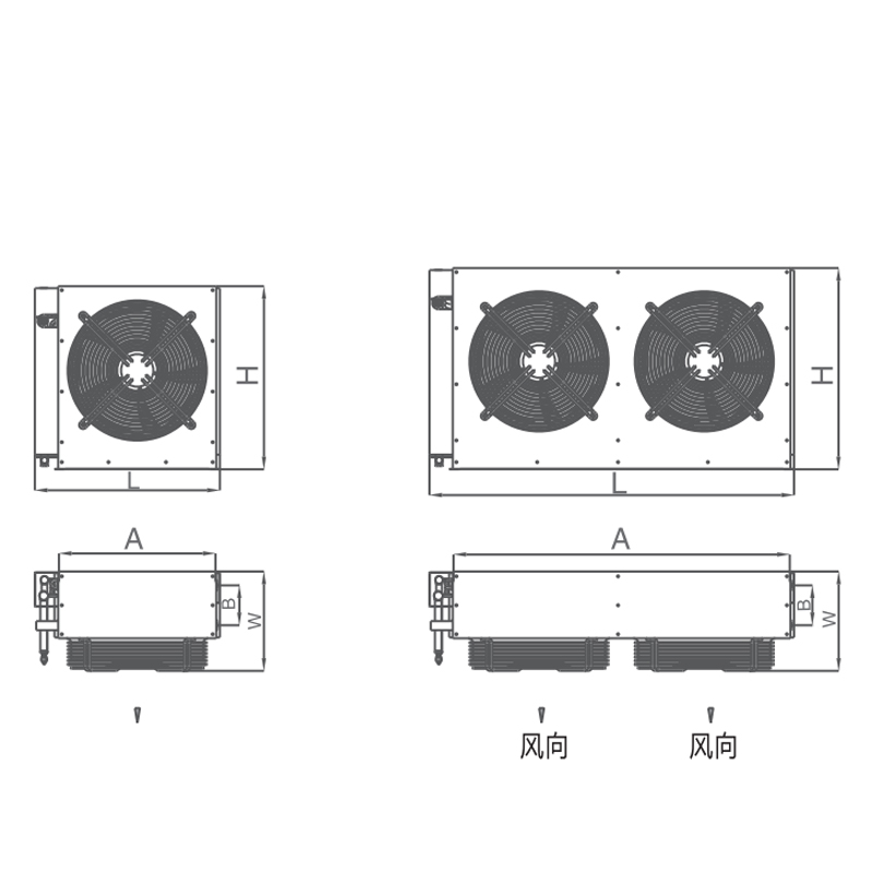
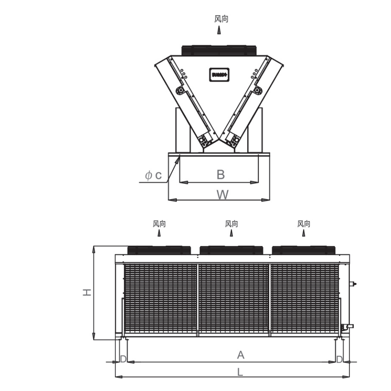
The Condenser Coil and Fan Assembly
The condenser coil is where heat extracted from the cold room interior is rejected to the surrounding environment. In air-cooled condensing units — which account for the vast majority of cold room refrigeration installations — one or more axial fans blow air across a finned copper or aluminum coil. The efficiency of heat rejection depends directly on the temperature difference between the ambient air and the condensing refrigerant temperature. When ambient temperatures rise above 35°C, many standard condensing units struggle to maintain their rated capacity, which is why high-ambient versions with larger condenser coils and more powerful fans exist for installations in hot climates or engine rooms.
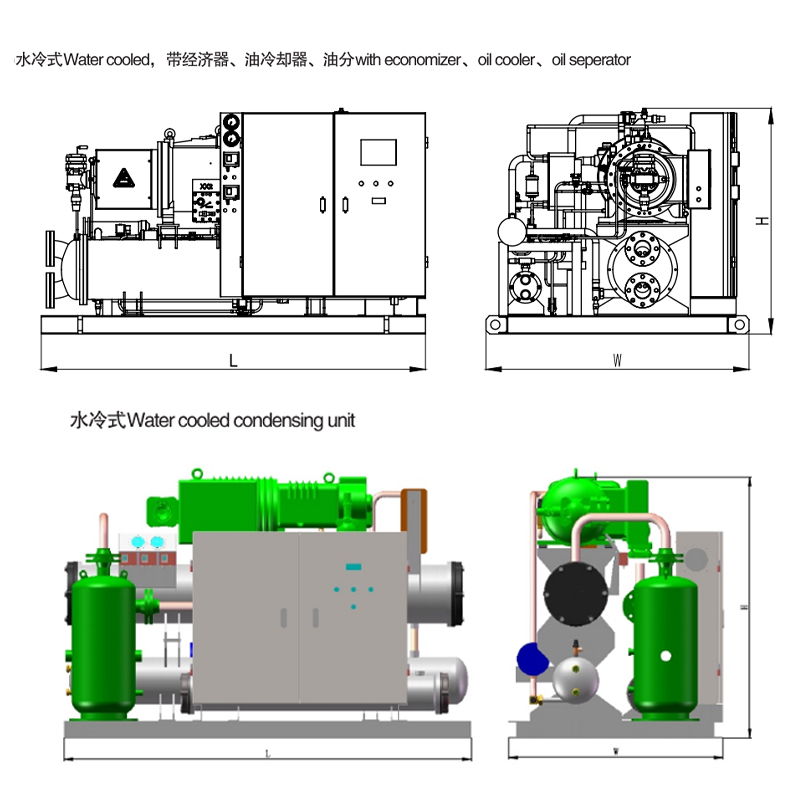
Water-cooled condensing units use a shell-and-tube or plate heat exchanger connected to a cooling water circuit instead of air. These are used when a condensing unit must be installed indoors without sufficient ventilation, or when extremely stable condensing temperatures are required. Water-cooled units are more compact and efficient but require a cooling tower or chiller circuit to supply cold water.
Receiver, Filter Drier, and Safety Controls
A well-specified condensing unit for cold room refrigeration includes a liquid receiver to buffer refrigerant charge variations, a filter drier to remove moisture and acid from the refrigerant circuit, a sight glass to verify liquid flow and system charge, a high-pressure safety switch, and a low-pressure safety switch. These components are standard on quality units from manufacturers such as Bitzer, Dorin, Frascold, and Copeland but may be absent on budget units, which then require field installation.
How to Size a Condensing Unit for a Cold Room
Correct sizing of the condensing unit is the single most important engineering decision in any cold room refrigeration project. An undersized condensing unit will run continuously, fail to reach setpoint, and burn out prematurely. An oversized unit wastes capital, cycles on and off too rapidly (short-cycling), and causes excessive humidity fluctuations inside the cold room that damage certain stored products.
Step 1 — Calculate the Total Heat Load
The heat load of a cold room is the sum of all heat sources that the refrigeration system must counteract to maintain the design temperature. These sources include:
- Transmission load — Heat conducted through walls, floor, ceiling, and doors. Calculated as: U-value × Area × Temperature difference. A 100 m² cold room at -20°C interior / +25°C exterior with 100 mm polyurethane panels (U = 0.23 W/m²K) might contribute approximately 1.5 kW from transmission alone.
- Product load — Heat removed from warm product being loaded into the cold room. This is often the dominant load for blast-chill operations but minimal for steady-state cold storage.
- Infiltration load — Warm, humid air that enters every time the cold room door opens. For busy distribution cold rooms with high door open frequency, this can account for 20–30% of total heat load.
- Internal loads — Heat from lighting, people working inside, forklifts, fans on the evaporator unit, and any other electrical equipment operating inside the cold room.
- Defrost heat — For low-temperature cold rooms, the electric or hot-gas defrost heaters on the evaporator add heat to the cold room during defrost cycles. This must be factored into the refrigeration load calculation.
Step 2 — Apply a Safety Factor and Select Operating Conditions
Once the total heat load is calculated, engineers typically apply a safety factor of 10–20% to account for calculation uncertainties and future load growth. The condensing unit is then selected from manufacturer performance data at the correct operating conditions:
- Saturated Suction Temperature (SST) — typically 8–10°C below the cold room setpoint
- Saturated Condensing Temperature (SCT) — typically 10–15°C above the maximum ambient temperature at the condensing unit location
For example, a cold room maintaining -18°C with a condensing unit located outdoors where the maximum ambient temperature is 35°C would require a condensing unit rated at approximately -28°C SST / +48°C SCT. Using manufacturer capacity tables at these conditions, rather than nominal conditions, avoids one of the most common cold room design errors.
Step 3 — Match the Evaporator to the Condensing Unit
The evaporator coil inside the cold room must be matched to the condensing unit capacity at the design conditions. The evaporator's rated capacity is also expressed at a specific temperature difference (TD) between the air entering the coil and the refrigerant evaporating temperature. A mismatch between evaporator and condensing unit capacity — even when both are nominally the same kW rating — leads to either an evaporator that cannot absorb heat fast enough or a condensing unit that constantly hunts for load and short-cycles.
Refrigerant Selection for Cold Room Refrigeration Systems
The phase-down of high-GWP refrigerants under the EU F-Gas Regulation and the Kigali Amendment to the Montreal Protocol has significantly changed refrigerant selection in cold room refrigeration. Understanding current and future-proof options is essential for anyone commissioning new cold room installations.
Legacy Refrigerants Being Phased Down
R-404A, formerly the most widely used refrigerant in cold room refrigeration condensing units, has a Global Warming Potential (GWP) of 3,922 — nearly 4,000 times more potent than CO₂ as a greenhouse gas. Under current EU regulations, R-404A is banned in new commercial refrigeration equipment and is subject to significant supply restrictions. Many countries outside the EU are implementing similar restrictions on schedule with the Kigali Amendment timeline. R-22, an older HCFC, is already fully banned for service use in most developed markets.
Current Drop-In and Low-GWP Alternatives
Several lower-GWP alternatives are now standard in new condensing units for cold room refrigeration:
- R-448A (Solstice N40, GWP 1387) and R-449A (Opteon XP40, GWP 1397) are the most widely adopted drop-in replacements for R-404A in medium and low-temperature cold room condensing units. They require compatible lubricant (POE oil) and some minor component checks but can be used in many existing systems retrofitted from R-404A.
- R-452A (Opteon XP44, GWP 2140) is a partial retrofit option with slightly higher GWP but very similar performance to R-404A, commonly used where a full conversion is not yet feasible.
- R-744 (CO₂) with a GWP of 1 is increasingly used in supermarket and industrial cold room refrigeration as a transcritical or subcritical system. CO₂ condensing unit systems require significantly higher pressures — transcritical discharge pressures can reach 90–120 bar — and specialized components, but the technology is now mature and cost-effective at scale.
- R-290 (propane) is a natural refrigerant with a GWP of 3 and excellent thermodynamic properties. Its flammability (A3 safety classification) limits charge sizes and requires explosion-proof components in the condensing unit, but for smaller cold rooms with charges under 150 g or in purpose-designed systems with larger charges using remote condensing units installed outdoors, R-290 is an excellent long-term choice.
The Next Generation: HFO and HFO Blends
HFO refrigerants like R-1234yf (GWP = 4) and HFO blends like R-454C and R-455A are entering the market specifically formulated for cold room refrigeration condensing units. R-455A (GWP 148) in particular is positioned as a long-term replacement for R-404A and R-448A in low-temperature cold room applications, offering a comparable performance profile with dramatically reduced environmental impact. Several major condensing unit manufacturers introduced R-455A-rated units in 2023–2024.
Condensing Unit Installation: Location, Ventilation, and Connection
Where and how a condensing unit is installed has a direct impact on cold room refrigeration performance, energy consumption, and equipment lifespan. Poor installation is responsible for a disproportionate share of cold room failures in the field.
Outdoor vs. Indoor Installation
Air-cooled condensing units are ideally installed outdoors in a shaded location with unrestricted airflow on all sides. The condenser fan draws air in from one face and exhausts it from another, so any obstruction within 1 meter of the discharge face risks recirculation — hot discharge air looping back to the inlet, driving up condensing temperature and reducing capacity. In practice, many cold room installations in retail or food service environments must mount condensing units indoors or in plant rooms, which requires deliberate ventilation design.
For indoor condensing units, the ventilation calculation must ensure that the heat rejected by the condensing unit (which is equal to the compressor power input plus the cold room heat load) can be removed by the ventilation airflow without allowing room temperature to exceed the design ambient. A condensing unit with a 5 kW cooling capacity and a 2.5 kW compressor power input rejects 7.5 kW of heat to the equipment room. If that room is not ventilated, temperatures will climb rapidly and the condensing unit will trip on high-pressure cutout.
Refrigerant Pipework: Line Sizing and Best Practices
The refrigerant suction line running from the evaporator in the cold room to the condensing unit outside is one of the most performance-critical elements of any cold room refrigeration installation. Undersized suction lines create excessive pressure drop, which lowers the effective suction pressure at the compressor and reduces capacity — every 1°C equivalent drop in suction pressure at -20°C SST can reduce system capacity by approximately 3–4%. Oversized suction lines on systems with vertical risers can prevent oil return to the compressor, leading to bearing damage over time.
The maximum recommended equivalent pipe length between evaporator and condensing unit varies by manufacturer but commonly falls in the range of 25–50 meters for residential and light commercial cold rooms, and up to 100 meters for purpose-designed industrial systems. Each 90° elbow adds equivalent length — typically 0.5–2 meters depending on pipe diameter — and must be counted in the total equivalent length calculation.
All refrigerant pipework must be insulated — the suction line to prevent condensation and heat gain from the environment, and the liquid line in hot climates or long runs to prevent flash gas formation before the expansion device. Suction line insulation thickness for low-temperature cold room refrigeration typically requires 19–25 mm of closed-cell foam insulation to be effective.
Electrical Supply Considerations
Condensing units for cold room refrigeration are available in single-phase (230V, 50 Hz) versions for smaller units up to approximately 3–4 kW cooling capacity, and three-phase (400V, 50 Hz) for larger units. Three-phase supply is preferred wherever possible because it allows smaller cable sizes, reduces starting current impacts, and improves compressor motor efficiency. Starting current (locked rotor current) for a condensing unit compressor is typically 5–7 times the full-load running current, which must be considered when sizing fuses, circuit breakers, and cable protection. Soft starters or variable-speed drives on larger condensing units significantly reduce starting current and are increasingly standard on premium units.
Energy Efficiency in Cold Room Refrigeration: EER, COP, and Variable Speed Technology
Energy consumption is a major operating cost in cold room refrigeration. For a medium-sized cold room operating continuously, the electricity bill over 10 years frequently exceeds the initial capital cost of the equipment. Energy efficiency therefore deserves serious attention at the specification stage.
Coefficient of Performance (COP) and Energy Efficiency Ratio (EER)
The Coefficient of Performance (COP) of a cold room refrigeration system is the ratio of useful cooling effect (in kW) delivered to the cold room divided by the electrical power consumed by the condensing unit (compressor plus condenser fans). A condensing unit operating at COP 2.5 delivers 2.5 kW of cooling for every 1 kW of electrical input. COP values for cold room condensing units vary widely with operating conditions:
- Medium-temperature cold room at +2°C with ambient +25°C: COP typically 2.5–3.5
- Low-temperature cold room at -18°C with ambient +25°C: COP typically 1.2–1.8
- Low-temperature cold room at -25°C with ambient +35°C: COP typically 0.8–1.1
These numbers illustrate why low-temperature cold room refrigeration is inherently energy-intensive — the fundamental thermodynamics of achieving large temperature differences require more compressor work.
Variable-Speed Compressors and EC Fan Motors
Variable-speed (inverter-driven) condensing units represent the most significant energy efficiency advancement in cold room refrigeration over the past decade. A conventional fixed-speed condensing unit operates at full capacity until the cold room reaches setpoint, then switches off. A variable-speed condensing unit modulates compressor speed and therefore capacity to match the actual heat load, running continuously at lower power when loads are light.
Field studies from supermarket and distribution center cold room installations consistently show energy savings of 25–40% compared to equivalent fixed-speed systems when variable-speed condensing units are installed. The additional upfront cost of a variable-speed unit is typically recovered in 2–4 years through reduced electricity bills, depending on energy tariff and utilization pattern.
Electronically commutated (EC) condenser fan motors are another high-impact efficiency upgrade. EC motors achieve efficiencies of 85–92% compared to 55–65% for conventional PSC motors. When combined with speed control based on head pressure, EC condenser fans can reduce fan power consumption by over 50% during cooler ambient conditions while also lowering condensing temperature and improving compressor efficiency.
Floating Head Pressure Control
Floating head pressure control allows the condensing unit to reduce its condensing pressure during cooler ambient conditions rather than maintaining a fixed minimum head pressure. Since compressor power consumption is directly related to the pressure ratio between suction and discharge, allowing head pressure to float down with ambient temperature can reduce compressor energy consumption by 2–4% for every 1°C reduction in condensing temperature. Over a year with seasonal temperature variation, floating head pressure control typically delivers energy savings of 10–15% compared to fixed head pressure operation.
Cold Room Refrigeration Controls: From Basic Thermostats to Smart Monitoring
Control technology for cold room refrigeration has evolved from simple electromechanical thermostats to sophisticated digital controllers with remote monitoring, alarm management, and energy analytics. The right control system protects product quality, reduces energy waste, and gives operators actionable information about system performance.
Digital Electronic Controllers
Digital controllers from manufacturers such as Dixell, Carel, and Eliwell are standard in commercial cold room refrigeration. These controllers manage compressor on/off or capacity modulation, defrost initiation and termination, evaporator fan operation, door open alarms, high-temperature alarms, and data logging. Most current models include NTC or PT1000 temperature sensor inputs, relay outputs for compressor and fans, and RS-485 Modbus or proprietary communication protocols for building management system integration.
A properly programmed controller should include a compressor minimum off-time delay of at least 3 minutes to prevent short-cycling, and a minimum on-time to ensure adequate oil return. Defrost scheduling should be time-based initially but ideally adapted based on evaporator pressure or demand signals to avoid unnecessary defrosts that waste energy and increase cold room temperature.
Remote Monitoring and HACCP Compliance
For food businesses, pharmaceutical cold rooms, and any application where product safety is regulated, continuous temperature monitoring and alarm notification is a regulatory requirement, not a luxury. Modern cold room refrigeration monitoring systems connect to cloud platforms via Wi-Fi, cellular, or Ethernet, providing real-time temperature dashboards, automated alarm notifications by SMS or email, and downloadable temperature logs for HACCP records. The EU Food Hygiene Regulations and FDA Food Safety Modernization Act (FSMA) both require documented temperature records for cold-stored foods, making a reliable data logging system a compliance necessity.
Some advanced monitoring platforms also track condensing unit parameters — suction pressure, discharge pressure, condensing unit superheat, and compressor run hours — enabling condition-based maintenance rather than calendar-based servicing. This approach can extend component life significantly. A compressor that is serviced based on actual run hours and operating condition data typically lasts 20–30% longer than one serviced on a fixed annual schedule regardless of actual operating history.
Common Faults in Cold Room Refrigeration and How to Diagnose Them
Most cold room refrigeration failures fall into a relatively small number of categories. Experienced technicians develop pattern recognition for these faults, using system pressures and temperatures as diagnostic tools rather than relying solely on symptoms reported by the cold room operator.
| Symptom | Likely Cause | Diagnostic Check | Remedy |
|---|---|---|---|
| Cold room too warm, high suction pressure | Refrigerant overcharge or TXV stuck open | Check superheat at evaporator outlet | Recover excess refrigerant or adjust/replace TXV |
| Cold room too warm, low suction pressure | Refrigerant undercharge or blocked filter drier | Check sight glass for bubbles; check pressure drop across drier | Find and fix leak, recharge; replace drier |
| High discharge pressure, tripping HP switch | Condenser fouled, recirculation, or ambient too high | Check condenser coil cleanliness and airflow clearances | Clean coil, improve ventilation, shade unit |
| Ice buildup on evaporator | Defrost failure or door seal problem | Check defrost termination sensor and heater continuity; inspect door seals | Replace defrost heater or sensor; replace door seal |
| Compressor short-cycling | Oversized system or controller differential too tight | Log compressor run and off times | Widen controller differential; consider hot gas bypass |
Refrigerant Leaks: The Most Costly and Underreported Problem
Refrigerant leaks are by far the most common cause of cold room refrigeration underperformance. Industry studies suggest that the average commercial refrigeration system loses between 10–15% of its refrigerant charge per year through small leaks at flare joints, brazed connections, valve packings, and Schrader valve cores. Each leak not only reduces system capacity but also costs money — refrigerant prices have increased sharply due to F-Gas quota restrictions, with R-404A reaching over £50/kg in the UK in some periods and similar spikes in other regulated markets.
Annual leak checking is mandatory under EU F-Gas Regulations for systems containing 5 tonnes CO₂ equivalent or more of refrigerant. Electronic leak detectors with sensitivity to 1 gram per year are the current standard for compliance checking. Given that a cold room condensing unit containing just 1.3 kg of R-404A already exceeds the 5 tonne CO₂e threshold (1.3 kg × 3922 GWP / 1000 = 5.1 tonnes CO₂e), virtually every commercial cold room condensing unit is subject to mandatory annual leak checks in regulated markets.
Preventive Maintenance Schedule for Cold Room Condensing Units
A well-maintained condensing unit in a cold room refrigeration system should last 10–15 years. Neglected units frequently fail within 5–7 years. The following maintenance schedule provides a practical framework for extending equipment life and minimizing unexpected downtime.
Monthly Tasks (Operator-Level)
- Visually inspect the condenser coil for debris, dust, or leaves blocking airflow. Even a partial blockage can raise condensing pressure by 3–5 bar and cut efficiency by 15%.
- Check that the condensing unit fan is operating and that no unusual noises are present from the compressor.
- Confirm cold room is maintaining setpoint temperature within the expected tolerance (typically ±1°C for medium temperature, ±2°C for low temperature).
- Review any alarm logs from the controller or monitoring system.
Annual Tasks (Qualified Refrigeration Technician)
- Full refrigerant leak test with electronic detector, documented for F-Gas compliance where applicable.
- Record operating pressures and temperatures at suction, discharge, and liquid line. Compare to previous year to identify trends indicating refrigerant loss or component wear.
- Check and record superheat at evaporator outlet and condenser outlet subcooling. These figures confirm that the refrigerant charge and expansion valve setting are correct.
- Clean condenser coil with appropriate coil cleaner and low-pressure rinse. A fouled condenser coil can increase compressor energy consumption by up to 25%.
- Check compressor oil level and color (if semi-hermetic). Acid test oil if water contamination is suspected.
- Inspect all electrical connections for tightness and signs of overheating. Loose connections are a leading cause of contactor and compressor terminal failures.
- Test all safety devices: high-pressure cut-out, low-pressure cut-out, and motor overloads. Verify that they trip at the correct setpoints and auto-reset or manual-reset as designed.
- Inspect and replace filter drier core if system moisture indicator (sight glass) shows yellow, or as a precaution every 2–3 years regardless.
Specifying the Right Condensing Unit: Key Parameters to Compare
When evaluating condensing units for a cold room refrigeration project, several technical parameters beyond the nominal kW rating determine whether a unit will perform as expected over its service life.
Maximum Ambient Temperature Rating
Standard condensing units are rated for operation up to 43°C or 46°C ambient. High-ambient versions are available rated to 55°C, which is necessary for Middle East, Southeast Asian, and rooftop installations in hot climates. Using a standard condensing unit in a location regularly exceeding 43°C ambient will result in chronic high-pressure trips, reduced capacity, and premature compressor failure.
Sound Power Level
For condensing units installed near residential areas, hotel kitchen areas, or any noise-sensitive location, sound power level is a critical specification. A standard condensing unit may have a sound power level of 65–72 dB(A). Low-noise versions with speed-controlled fans and acoustic compressor blankets can reduce this by 5–10 dB(A), which is a significant difference perceptually. Many local planning and building regulations specify maximum permitted noise levels from refrigeration equipment, making this a legal compliance issue, not just a comfort consideration.
Protection Class and Corrosion Resistance
Condensing units for cold room refrigeration are available in standard versions for typical outdoor installation, and in versions with enhanced corrosion protection for coastal, food processing, or chemical environments. Epoxy-coated condenser coils, stainless steel or powder-coated galvanized steel cabinets, and marine-grade electrical enclosures can more than double the service life of a condensing unit in aggressive environments. The additional cost — typically 15–25% over standard specification — is almost always justified by avoided replacement costs.
Connectivity and Smart Features
Leading condensing unit manufacturers now offer units with integrated Modbus, BACnet, or proprietary IoT connectivity, allowing the condensing unit to report compressor run hours, operating pressures, temperatures, and fault codes directly to building management systems or cloud monitoring platforms. Brands like Danfoss (Optyma Plus range), Bitzer (ORBIT screw condensing units), and Emerson (Copeland Stream) offer factory-integrated connectivity on many product lines, eliminating the need for field-installed monitoring sensors on individual components.
Cold Room Insulation and Its Relationship to Condensing Unit Selection
The insulation quality of a cold room directly determines the transmission heat load and therefore the size of condensing unit required. Investing in higher-specification insulation panels reduces the required condensing unit size, reduces running costs, and improves temperature stability — a virtuous cycle that is often underappreciated in low-bid procurement processes.
Standard cold room panels use 80 mm polyurethane foam with a thermal conductivity (lambda) of approximately 0.023 W/mK, giving a U-value around 0.28 W/m²K. Upgrading to 100 mm panels reduces U-value to approximately 0.23 W/m²K, and 150 mm panels (used for low-temperature freezer rooms) achieve U-values around 0.15 W/m²K. For a 50 m² cold room wall area with a 45°C temperature difference between inside and outside, the difference in transmission load between 80 mm and 150 mm panels is approximately 360 W — significant enough to downsize the condensing unit by one model in many product ranges.
Door design is equally important. Cold room doors account for a disproportionate share of heat infiltration relative to their area, especially in high-traffic applications. Strip curtains reduce door infiltration load by approximately 75% compared to an uncurtained doorway, and air curtains achieve similar or better performance while maintaining easier pedestrian access. Automatic door closers and door open alarms are essential in any cold room used by multiple operators to prevent accidental door-open events that can warm an entire cold room in minutes and trigger unnecessary condensing unit overload.


