

 English
 中文简体
中文简体Content
- 1 What An Evaporator Does Inside A Refrigeration System
- 2 How The Evaporator Coil Removes Heat
- 3 Types Of Evaporators Used In Refrigeration
- 4 Direct Expansion Versus Flooded Evaporators
- 5 Materials And Construction Of Evaporator Coils
- 6 Fin Design And Airflow Engineering
- 7 Evaporator Superheat And Why It Matters
- 8 Liquid Quality And Subcooling Entering The Evaporator
- 9 Frost And Defrost Cycles On Evaporator Coils
- 10 Common Evaporator Problems And Troubleshooting
- 11 Evaporator Sizing And Capacity Matching
- 12 Refrigerant Selection And Evaporator Performance
- 13 Evaporator Applications Across Refrigeration Industries
- 14 Energy Efficiency Considerations For Evaporator Operation
- 15 Installation Best Practices For Evaporator Coils
- 16 Maintenance Practices That Extend Evaporator Life
- 17 Frequently Asked Questions About Evaporators In Refrigeration
- 17.1 What is the difference between an evaporator and a condenser?
- 17.2 Why is my evaporator coil freezing up?
- 17.3 How often should an evaporator coil be cleaned?
- 17.4 What temperature should an evaporator run at?
- 17.5 Can an evaporator be too large for a system?
- 17.6 What causes water leaking from underneath a refrigeration unit?
- 17.7 How long should a defrost cycle take?
- 17.8 Does evaporator fin spacing affect energy use?
- 17.9 Why does an evaporator need a specific refrigerant charge?
- 17.10 Can an evaporator coil be repaired instead of replaced?
What An Evaporator Does Inside A Refrigeration System
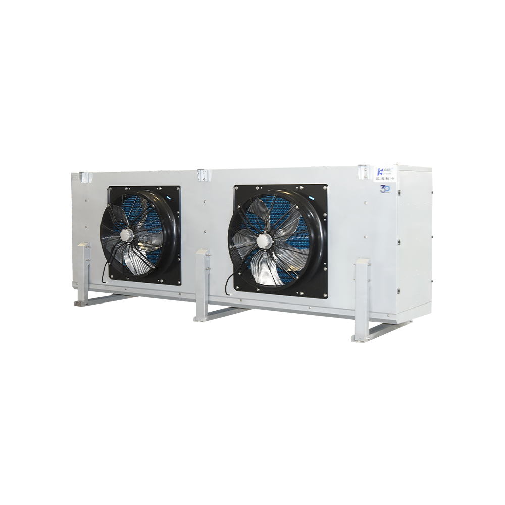
The evaporator is the component that actually produces the cooling effect in a refrigeration system. Inside the evaporator coil, liquid refrigerant absorbs heat from the air, water, or product surrounding it and boils into a low-pressure vapor. This heat absorption is the entire reason cold storage, display cases, and air conditioning equipment feel cold — the compressor, condenser, and expansion device exist mainly to prepare refrigerant for this single moment inside the evaporator.
An evaporator in refrigeration typically operates at a saturation temperature roughly 5°C to 10°C below the desired space temperature. A walk-in cooler held at 2°C, for example, commonly runs an evaporator coil temperature near -4°C to -6°C, depending on humidity targets and product type. Once refrigerant leaves the evaporator as low-pressure vapor, it travels to the compressor, where the cycle continues.
Although the evaporator is sometimes described as the "cold side" of the system, the coil itself does not generate cold in the way a heater generates heat. Instead, it relies entirely on the physical property that liquids absorb large amounts of energy when changing phase to a gas. This property, known as latent heat of vaporization, allows a relatively small mass of refrigerant to absorb a disproportionately large amount of heat compared to simply warming a liquid or gas without a phase change. That is why refrigeration cycles are dramatically more energy efficient at moving heat than electric resistance heating would be at generating an equivalent temperature difference.
Every refrigeration application, from a household freezer to a multi-megawatt industrial ammonia plant, depends on this same basic evaporator principle. What changes between applications is the coil geometry, the airflow or liquid flow arrangement, the refrigerant selected, and the control strategy used to meter refrigerant into the coil. Understanding these variables is the foundation for selecting, installing, and troubleshooting evaporators correctly.
Direct answer: an evaporator's job is heat absorption through refrigerant boiling, converting warm air or liquid into a cooled medium while the refrigerant itself changes from liquid to vapor.
How The Evaporator Coil Removes Heat
Heat transfer at the evaporator follows a predictable sequence. Warm air or liquid passes across the outside of the coil while cold liquid refrigerant flows inside the tubing. Because the refrigerant's boiling point is far lower than the surrounding temperature, it absorbs heat through the tube wall and changes phase from liquid to gas.
Liquid Refrigerant Enters
Low-pressure liquid refrigerant, metered by the expansion valve or capillary tube, enters the evaporator inlet at a temperature lower than the surrounding air. At this stage the refrigerant is usually a mixture of liquid and a small amount of flash gas created during the pressure drop across the metering device.
Boiling Begins
As the refrigerant absorbs heat through the coil wall, it starts boiling and converting to vapor along the length of the coil circuit. This boiling zone typically occupies 70 to 85 percent of the total coil length in a properly fed direct expansion evaporator.
Superheat Develops
Near the coil outlet, all liquid has vaporized, and the remaining gas continues absorbing a small amount of additional heat, called superheat. This final stretch of the coil, sometimes called the superheat horn, is shorter but still contributes to overall capacity.
Vapor Exits To Suction Line
Fully vaporized, superheated refrigerant leaves through the suction line toward the compressor, completing the heat-removal stage of the cycle. The temperature and pressure of this vapor are exactly what a technician measures when verifying system performance.
The rate at which heat moves from the surrounding air into the refrigerant depends on several variables working together: the temperature difference between the air and the refrigerant, the surface area of the coil exposed to airflow, the velocity of air moving across the fins, and the cleanliness of both the fin surface and the refrigerant-side tube wall. Engineers express this relationship using an overall heat transfer coefficient, often written as U, multiplied by surface area and temperature difference to estimate total capacity in watts or BTU per hour.
Types Of Evaporators Used In Refrigeration
Evaporator design varies by application, airflow requirement, and the product being cooled. The table below summarizes the most common configurations found in commercial and industrial refrigeration.
| Evaporator Type | Typical Use | Airflow Method |
|---|---|---|
| Forced-air (fan coil) | Walk-in coolers, freezers, reach-in cases | Fan-driven |
| Natural convection (bare tube/plate) | Wine storage, low-velocity humidity-sensitive rooms | Gravity-driven |
| Plate evaporator | Blast freezing, liquid chilling | Direct contact or liquid flow |
| Shell-and-tube | Chillers cooling water or glycol | Liquid-to-refrigerant |
| Plate-fin (finned tube) | Supermarket cases, air handlers | Fan-driven, high surface area |
| Plate-and-frame | Compact liquid chilling, dairy and beverage processing | Counter-flow liquid streams |
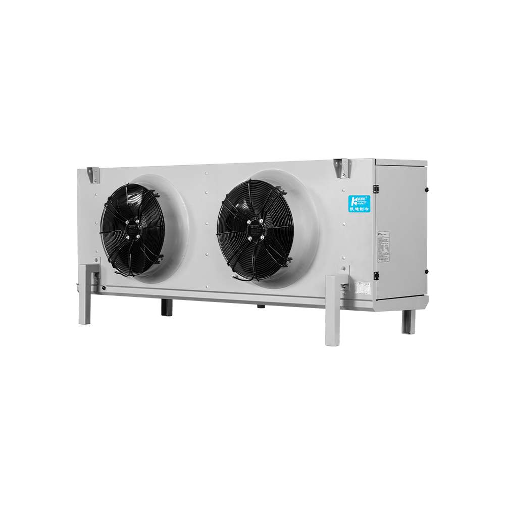
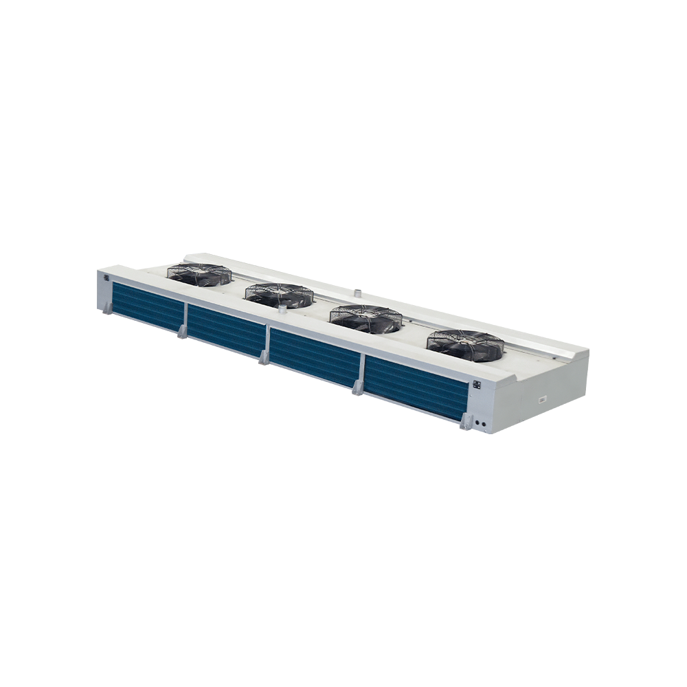
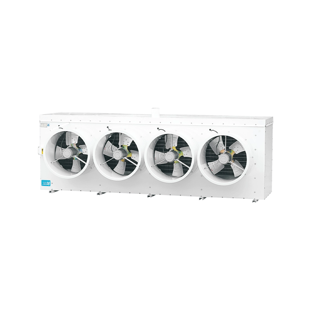
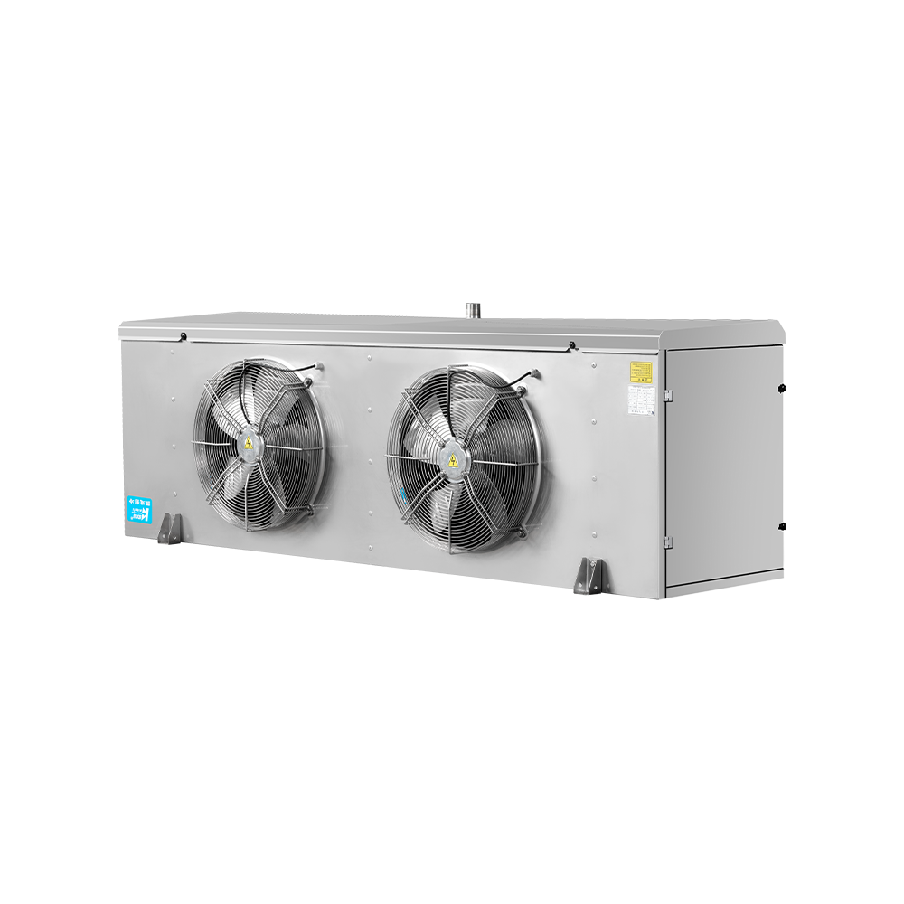
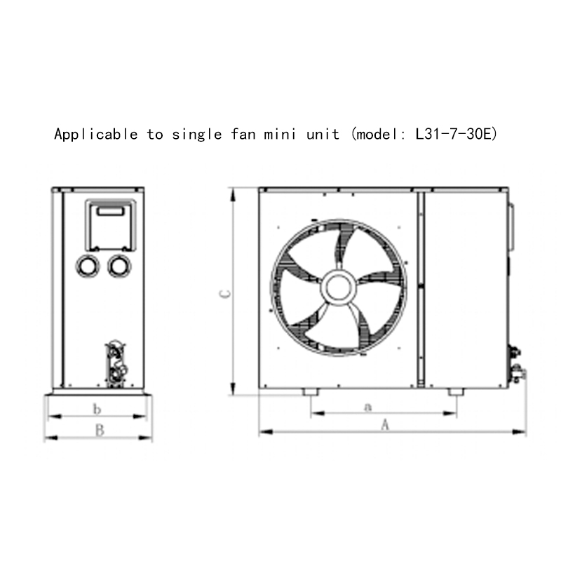
Finned-tube forced-air evaporators remain the most widely installed type in commercial refrigeration because they balance compact size with strong heat transfer per unit volume, especially when fin spacing is tuned for the expected frost accumulation rate. Bare-tube and plate-style natural convection evaporators trade some capacity density for quieter, lower-velocity operation, which suits humidity-sensitive storage where rapid air movement would otherwise dry out unpackaged products.
Shell-and-tube and plate-and-frame evaporators belong to a different category entirely, since they cool a liquid secondary refrigerant such as water, glycol, or brine rather than cooling air directly. These liquid chillers then circulate the cooled fluid to air handlers or process equipment elsewhere in the facility, which is common in large supermarkets, breweries, and dairy plants where centralizing the refrigeration plant reduces total refrigerant charge and simplifies leak management.
Direct Expansion Versus Flooded Evaporators
Direct Expansion (DX)
- Refrigerant fully evaporates inside the coil before exiting
- Controlled by a thermostatic or electronic expansion valve
- Lower refrigerant charge requirement
- Most common configuration in commercial cooling equipment
- Simpler piping layout with fewer auxiliary components
Flooded Evaporator
- Coil stays filled with liquid refrigerant at all times
- A surge drum separates liquid from returning vapor
- Delivers very even surface temperature across the coil
- Common in large industrial ammonia systems
- Generally requires a liquid recirculation pump
Flooded systems generally achieve higher heat transfer coefficients than direct expansion coils of the same surface area because the tube walls stay continuously wetted with liquid refrigerant rather than transitioning to vapor partway through the circuit. The tradeoff is a larger total refrigerant charge and additional equipment such as a surge drum and liquid pump.
A third configuration worth noting is the liquid overfeed evaporator, sometimes treated as a variant of the flooded design. Liquid overfeed systems deliberately pump more liquid refrigerant through the coil than will fully evaporate, typically at an overfeed ratio between two-to-one and four-to-one. The excess liquid returns to a central low-pressure receiver for separation and recirculation. This approach is favored in large cold storage warehouses and food processing plants because it keeps coil surfaces consistently wetted, reduces the risk of dry spots, and simplifies defrost performance across many distributed evaporators fed from one central plant.
Materials And Construction Of Evaporator Coils
Most commercial evaporator coils use copper tubing combined with aluminum fins, a pairing chosen because copper offers excellent thermal conductivity and corrosion resistance on the refrigerant side, while aluminum fins keep weight and material cost lower on the air side. Tube diameters in commercial coils commonly range from 3/8 inch to 5/8 inch, with smaller diameters favored in compact display cases and larger diameters used where higher refrigerant flow rates are needed.
In food processing or marine environments where corrosion resistance becomes critical, manufacturers often switch to all-aluminum coils, copper tube with copper fins, or apply protective coatings such as epoxy or e-coating over standard aluminum fins. Stainless steel construction appears in some plate evaporators used for direct liquid chilling in dairy and beverage applications, since stainless surfaces tolerate frequent washdown with cleaning chemicals far better than untreated aluminum.
Fin spacing, typically measured in fins per inch (FPI), is one of the most consequential design decisions for any forced-air evaporator. Coils intended for low-temperature freezer applications, where frost accumulates quickly, commonly use wider fin spacing between 3 and 6 FPI to leave room for ice growth between defrost cycles. Coils for medium-temperature cooler applications with less frost accumulation can use tighter spacing between 8 and 14 FPI, packing more surface area into the same physical footprint to increase capacity.
Fin Design And Airflow Engineering
Beyond simple fin spacing, evaporator manufacturers refine fin geometry to maximize turbulence and surface contact without creating excessive airflow resistance. Common fin patterns include flat plate fins, louvered fins, and wavy or corrugated fins. Louvered and wavy fin geometries disrupt the boundary layer of air moving across the surface, improving the convective heat transfer coefficient compared to a flat fin of the same spacing, though they also increase static pressure drop and fan energy use.
Circuit design inside the coil matters just as much as the external fin geometry. A coil with too few refrigerant circuits relative to its face area creates excessive pressure drop and uneven refrigerant distribution, while too many circuits can starve individual tubes of adequate refrigerant velocity, reducing the internal heat transfer coefficient. Engineers typically design circuiting around the specific refrigerant, expected mass flow rate, and target pressure drop, often using a feeder or distributor device immediately after the expansion valve to split refrigerant evenly among multiple circuits.
Fan selection works hand in hand with fin and circuit design. Axial fans are common in smaller reach-in and walk-in evaporators because they move large air volumes at relatively low static pressure, while centrifugal blowers appear in ducted applications or coils with tighter fin spacing that create higher resistance to airflow. Matching fan curve to coil pressure drop ensures the unit delivers its rated airflow in actual field conditions rather than only under laboratory test conditions.
Evaporator Superheat And Why It Matters
Superheat is the temperature rise of refrigerant vapor above its saturation point after it has fully boiled inside the evaporator. It is one of the most important values a refrigeration technician checks during commissioning and service work.
Typical target range: 4°C to 8°C (7°F to 14°F) of superheat for most direct expansion air-cooling applications.
Why it is checked: too little superheat risks liquid refrigerant reaching the compressor; too much superheat signals the coil is starved and not using its full surface area for heat absorption.
Low superheat readings, generally under 3°C, often point to an overfeeding expansion device or a coil that is oversized for the load. High superheat, often above 10°C, frequently indicates a restricted filter drier, undersized expansion valve, low refrigerant charge, or airflow that is too aggressive across an undersized coil. Technicians typically measure superheat by comparing the suction line temperature at the coil outlet against the saturation temperature read from suction pressure on a pressure-temperature chart for the specific refrigerant in use.
Two distinct superheat values are referenced in field service: static superheat, measured directly at the evaporator outlet before any suction line pressure drop or heat gain, and total superheat, measured at the compressor inlet after the suction line. Thermostatic expansion valves are typically set to maintain static superheat at the coil outlet, while electronic expansion valves can be programmed to target either value depending on the controller logic. The difference between the two readings, sometimes several degrees on long suction line runs, helps technicians distinguish between an expansion valve problem at the coil and a suction line insulation or sizing problem elsewhere in the system.
Liquid Quality And Subcooling Entering The Evaporator
While superheat describes conditions leaving the evaporator, the condition of refrigerant entering the coil also affects performance. Refrigerant should arrive at the expansion device as a subcooled liquid, meaning its temperature is below the saturation temperature corresponding to its pressure, with little or no flash gas already present. Typical subcooling targets at the condenser outlet range from 5°C to 10°C, depending on system design and refrigerant type.
Insufficient subcooling allows flash gas to form in the liquid line before the refrigerant ever reaches the expansion valve, reducing the valve's effective capacity and starving the evaporator even when the valve itself is functioning correctly. Long liquid line runs, elevation changes where refrigerant rises significantly before reaching the evaporator, and undersized liquid line diameter are common contributors to excessive pressure drop and resulting flash gas formation. Field technicians troubleshooting an evaporator that appears starved should always verify subcooling and liquid line conditions before assuming the expansion valve itself is defective.
Frost And Defrost Cycles On Evaporator Coils
Any evaporator running below 0°C surface temperature in a humid environment will accumulate frost. A thin frost layer under roughly 3mm thick has minimal effect on performance, but thicker buildup insulates the coil and blocks airflow between fins, reducing capacity significantly.
| Frost Thickness | Estimated Capacity Loss |
|---|---|
| 1-2mm | Minimal, under 5% |
| 3-5mm | 10-20% |
| 6-10mm | 25-40% |
| Over 10mm | 40% or more, restricted airflow |
Defrost methods commonly used on evaporator coils include off-cycle defrost for medium-temperature applications above roughly 2°C, electric heater defrost for low-temperature freezer coils, and hot gas defrost, which routes warm discharge refrigerant through the coil to melt frost quickly while reducing electrical demand compared to resistance heaters.
Defrost frequency and duration are normally set by a time clock, an air pressure differential switch across the coil, or a combination of both in more advanced controllers. Time-initiated, temperature-terminated defrost is a widely used strategy: defrost begins on a fixed schedule, often every four to eight hours for freezer coils, but ends as soon as a sensor on the coil detects that ice has melted, rather than running for a fixed duration regardless of actual frost load. This approach reduces unnecessary energy use and limits the amount of heat introduced into the cold space compared to fixed-duration defrost timers.
Hot gas defrost in particular requires careful piping design, including a check valve arrangement and sometimes a dedicated defrost relief regulator, to prevent liquid refrigerant from slugging back to the compressor when the defrost cycle ends and the system returns to normal cooling operation. Poorly designed hot gas defrost piping is a common source of compressor valve damage in industrial ammonia and CO2 systems if not engineered correctly.
Common Evaporator Problems And Troubleshooting
Reduced Cooling Capacity
Usually traced to airflow restriction from dirty coils or failing fan motors, low refrigerant charge, or excessive frost buildup blocking fin spacing.
Iced-Over Coil
Often caused by a failed defrost timer or heater, airflow blockage from blocked return vents, or chronic low superheat flooding the coil with liquid refrigerant.
Excess Moisture Or Water Stains Near The Unit
Frequently linked to a clogged condensate drain line, an improperly pitched drain pan, or a missing drain pan heater in freezer applications.
Uneven Cooling Across The Space
Can result from undersized fan coverage, poor coil placement relative to airflow patterns, or a coil that is undersized for the room's heat load.
Unusual Noise From The Coil Section
Often caused by a worn fan motor bearing, a fan blade striking ice buildup, or refrigerant flooding through the coil and into the suction line, sometimes audible as a gurgling or hissing sound.
Short Cycling Or Frequent On-Off Operation
Commonly tied to an oversized evaporator relative to the load, a misadjusted thermostat differential, or a defrost termination sensor that ends cycles prematurely before ice has fully cleared.
Systematic troubleshooting typically begins with verifying airflow first, since blocked or reduced airflow is the single most common evaporator complaint across commercial refrigeration, before moving on to refrigerant-side measurements such as suction pressure, superheat, and subcooling. Skipping the airflow check and jumping directly to refrigerant charge adjustments is a frequent cause of misdiagnosis, since adding refrigerant to compensate for poor airflow often masks the underlying problem while creating a separate overcharge condition.
Evaporator Sizing And Capacity Matching
An evaporator's rated capacity must match the calculated heat load of the space, not just the compressor's capacity. Refrigeration engineers typically size the evaporator first, then select a compressor and condenser that match the coil's design temperature difference, abbreviated TD — the gap between the coil's saturated suction temperature and the room's desired air temperature.
- Calculate total heat load, including product load, infiltration, lighting, and equipment heat
- Select a coil TD appropriate to the application, commonly 5-7°C for low humidity tolerance or 8-12°C for produce storage requiring lower humidity sensitivity
- Match the coil's rated BTU/hr or kW output at that TD to the calculated load with a reasonable safety margin, typically 10-15%
- Confirm airflow in CFM or m³/h is sufficient for the room volume and air change rate required
- Verify the selected coil's defrost method matches the expected operating temperature and humidity exposure
A smaller coil TD, meaning the evaporator runs closer to room temperature, preserves humidity and reduces moisture loss from stored products such as fresh produce, but it generally requires a larger coil surface area and higher equipment cost to achieve the same capacity.
Manufacturers publish capacity ratings under standardized test conditions, often based on a specific suction temperature, entering air temperature, and refrigerant type. When comparing coils from different suppliers, it is important to confirm that published ratings use comparable test conditions, since a coil rated at a wider TD will show a higher nominal capacity number even if its actual performance at a narrower, more humidity-friendly TD is lower than a competing coil designed specifically for that narrower range.
Refrigerant Selection And Evaporator Performance
The refrigerant circulating through an evaporator directly affects coil sizing, operating pressure, and capacity. Common refrigerants used in commercial and industrial evaporators today include R-448A and R-449A as lower global warming potential replacements for older R-404A systems, R-290 propane in small self-contained units, R-744 carbon dioxide in transcritical and subcritical industrial systems, and ammonia (R-717) in large industrial cold storage plants.
Each refrigerant has a distinct pressure-temperature relationship, which means coils are not universally interchangeable between refrigerant types without re-evaluating circuit design, tube wall thickness, and expansion device sizing. CO2 systems, for example, operate at substantially higher pressures than HFC or HFO refrigerants, requiring heavier-wall tubing and components rated for that higher working pressure. Ammonia, by contrast, has excellent thermodynamic properties and a very high latent heat of vaporization, which often allows smaller refrigerant mass flow rates for a given capacity, but it requires specific material compatibility since ammonia is incompatible with copper and most copper alloys, so ammonia evaporator coils are built from steel or aluminum instead.
Flammability classification also affects evaporator and system design. Refrigerants such as R-290 are classified as A3, meaning higher flammability, which typically limits the refrigerant charge allowed in a single circuit and influences where the evaporator and its refrigerant-containing components can be installed relative to occupied space and ignition sources, following applicable safety standards for the region and application.
Evaporator Applications Across Refrigeration Industries
Food Retail And Supermarkets
Open and closed display cases use finned-tube evaporators tuned for frequent door openings, glass door radiant heat gain, and strict temperature uniformity requirements across long case runs.
Cold Storage Warehousing
Large industrial facilities often rely on liquid overfeed or flooded ammonia evaporators distributed across multiple rooms, fed from a centralized engine room for efficiency at scale.
Food Processing And Blast Freezing
Plate evaporators and high-velocity forced-air units handle rapid heat removal from product, often targeting core temperature reduction within a defined time window for food safety compliance.
Transport Refrigeration
Compact forced-air evaporators in refrigerated trucks and containers must tolerate vibration, frequent door openings, and variable ambient conditions while maintaining tight temperature control for perishable cargo.
Comfort Air Conditioning
Residential and commercial air conditioning evaporator coils prioritize moisture removal alongside sensible cooling, since dehumidification significantly affects occupant comfort.
Beverage And Dairy Processing
Plate-and-frame liquid chillers cool process fluids rapidly while withstanding frequent washdown cycles required for food-grade sanitation standards.
Energy Efficiency Considerations For Evaporator Operation
Evaporator design and maintenance directly influence overall system energy consumption, since the coil's operating temperature difference has a compounding effect on compressor energy use. Generally, every 1°C reduction in compressor suction temperature, often driven by a tighter evaporator TD or fouled coil surface, increases compressor energy consumption by roughly 2 to 4 percent for a given cooling load, depending on the system and refrigerant involved.
Selecting a larger coil with a narrower design TD reduces this energy penalty by allowing the system to operate at a warmer suction temperature for the same room temperature target, though the tradeoff is higher upfront equipment cost and a larger physical footprint. Facilities focused on long-term operating cost, particularly cold storage warehouses running continuously throughout the year, often find that the energy savings from an oversized, low-TD evaporator pay back the additional capital cost within a few years of operation.
Electronically commutated (EC) fan motors are increasingly specified on new evaporator units in place of traditional shaded-pole or permanent split capacitor motors, since EC motors can reduce fan energy consumption by 50 percent or more while also enabling variable-speed control that reduces airflow, and therefore energy use and product dehydration, during periods of lower heat load.
Installation Best Practices For Evaporator Coils
Maintain Proper Airflow Clearance
Leave adequate space around the coil intake and discharge to avoid recirculating already-cooled air, which reduces effective capacity and skews temperature readings.
Pitch The Coil For Drainage
Install the coil and drain pan with a slight pitch toward the drain connection so condensate and defrost water flow out completely rather than pooling and refreezing.
Insulate And Trap The Suction Line
Properly insulate the suction line leaving the evaporator to prevent unwanted heat gain that distorts superheat readings, and include appropriate oil return traps on vertical risers.
Locate Sensors Away From Direct Airflow Disturbance
Position defrost termination sensors and thermostats where they accurately represent coil and space conditions, avoiding spots influenced by door openings or direct sunlight.
Maintenance Practices That Extend Evaporator Life
Coil Cleaning
Inspect and clean fins quarterly in high-grease or dusty environments, and at minimum twice yearly in clean indoor spaces, since blocked fins reduce airflow and force the system to run longer cycles.
Drain Line Flushing
Flush condensate lines on a routine schedule to prevent algae or debris clogs that lead to overflow and water damage near the unit.
Fan Motor Checks
Listen for bearing noise and check amperage draw against nameplate ratings during routine service visits to catch motor wear before failure.
Superheat Verification
Recheck superheat readings seasonally, since ambient temperature swings shift expansion valve behavior and can reveal slow refrigerant leaks early.
Door Gasket And Seal Inspection
Check walk-in door gaskets and curtain strips regularly, since infiltration from poor seals adds latent and sensible load directly onto the evaporator coil.
Defrost Heater And Termination Sensor Testing
Verify defrost heaters reach proper temperature and termination sensors end the cycle correctly, since a stuck sensor can leave a coil iced over or waste energy running excess defrost time.
Establishing a written maintenance log for each evaporator, recording superheat, suction pressure, coil condition, and fan amperage at each visit, helps technicians identify gradual performance drift long before it becomes a full system failure. Trend data is particularly valuable for catching slow refrigerant leaks, which often show up first as a gradual rise in superheat over several months rather than a sudden, obvious symptom.
Frequently Asked Questions About Evaporators In Refrigeration
What is the difference between an evaporator and a condenser?
The evaporator absorbs heat from the surrounding space as refrigerant boils at low pressure, while the condenser releases that absorbed heat to the outside air or water as refrigerant condenses at high pressure. They perform opposite functions within the same refrigeration cycle.
Why is my evaporator coil freezing up?
Coil icing is typically caused by restricted airflow from dirty filters or blocked vents, a malfunctioning defrost system, or low refrigerant charge causing the coil to run colder than designed across its full surface.
How often should an evaporator coil be cleaned?
Most commercial coils benefit from cleaning every three to six months, though kitchens and processing areas with heavy grease or dust in the air often need monthly inspection to avoid significant airflow loss.
What temperature should an evaporator run at?
Evaporator coil temperature generally runs 5°C to 10°C below the target room or product temperature, though the exact design TD depends on humidity requirements and the type of product being stored.
Can an evaporator be too large for a system?
Yes. An oversized evaporator paired with an undersized compressor can struggle to maintain proper superheat, leading to liquid refrigerant returning toward the compressor and potential long-term damage if not corrected with proper expansion valve sizing.
What causes water leaking from underneath a refrigeration unit?
Leaking water is most often caused by a clogged or improperly sloped condensate drain line, a cracked drain pan, or frozen condensate that later melts and overflows the pan.
How long should a defrost cycle take?
Typical electric or hot gas defrost cycles run between 20 and 40 minutes, though the exact duration depends on coil size, frost load, and whether the controller uses temperature-terminated logic to end the cycle as soon as the coil clears.
Does evaporator fin spacing affect energy use?
Yes. Tighter fin spacing increases surface area and can improve capacity, but it also raises airflow resistance and fan energy consumption, while wider spacing in freezer applications reduces frost-related airflow blockage between defrost cycles.
Why does an evaporator need a specific refrigerant charge?
The refrigerant charge determines how much liquid is available to properly feed the coil and maintain correct superheat; both undercharge and overcharge conditions disrupt the balance between evaporator capacity and expansion device control.
Can an evaporator coil be repaired instead of replaced?
Minor leaks at accessible fittings or small sections of tubing can often be repaired, but coils with widespread corrosion, multiple leak points, or significant fin damage are typically more cost-effective to replace than repair.